Mettler Toledo XP Balance: Fixing Flash Corruption Without Manufacturer Support
Introduction
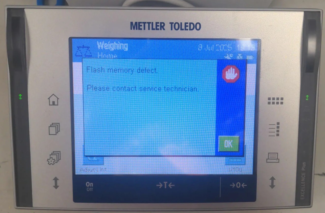
The Mettler Toledo XP Analytical Balance showing an flash memory error.
Like many good projects, this started with a random stranger asking for help on the Internet. In this case, it was seeigecannon posting in the IoT Hacker Hideout Discord server about a Mettler Toledo XP Series analytical balance that was throwing a “Program Memory” error.
These things are not cheap. A Mettler Toledo XP-series analytical balance can easily run $2000-5000 on the used market. So when seeigecannon’s scale started showing this error, he looked online and was lucky to find a service manual for a similar device. The manual does actually document a firmware flashing procedure using MT’s own e-Loader II software, so a firmware restore should in theory be a valid repair path. The problem: MT stopped supporting the XP series in 2022 and scrubbed e-Loader II from their site along with it. When seeigecannon reached out to them, they couldn’t even send him the firmware file. The only official fix left in the manual was to replace the entire controller board. But with support ended, sourcing that part would be difficult if not impossible. Even if he could find one, it felt excessive for what might just be a software problem. So after trying a few things on his own, he reached out to the community for help.
I’m always up for a good repair, and if I can make use of my reverse engineering skills to get there, even better. What made this even more interesting is that I never had physical access to the device. So let’s dig in.
Meet the Hardware
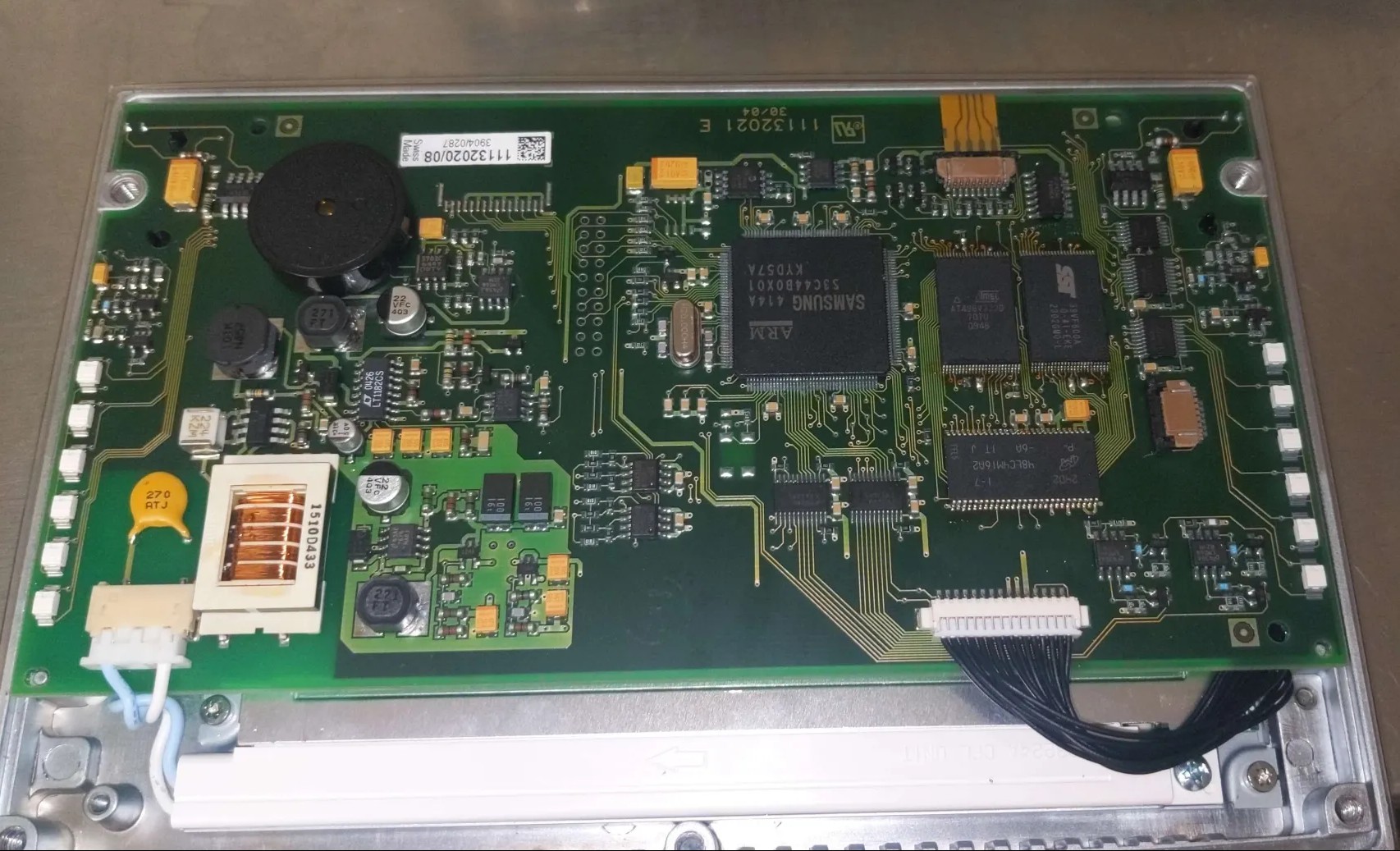 The Mettler Toledo XP Analytical Balance controller board.
The controller board is built around a Samsung S3C44B0X, an ARM v4T MCU. It has no internal flash, which means the entire firmware has to live somewhere external. In this case that’s an AT49BV322 TSOP48 flash chip, a 4MB parallel NOR flash. There is also an additional SST39VF800A Flash chip on the board, but that one is just for storing the “User Data” and doesn’t contain any executable code, so we can ignore it for now.
The good news: it’s a well-known part, and dumping it with a flash programmer is straightforward.
The bad news is that seeigecannon had three of these boards and all three dumps looked completely different from each other. Not slightly different, wildly different. That’s not what you expect if you’re hoping to find a clean copy to restore from. He had verified the dumps by doing a second read and comparing the checksums, so the dumps themselves were consistent.
One board was his original failing scale. Another came from a lab he was friendly with, also failing with the same error. The third was an eBay controller he had picked up, but this seemed to be on a completely different hard- and firmware revision.
At this point the plan was simple: We needed to figure out what was actually wrong with those flash memories.
Into Ghidra
The first thing to do with an unknown firmware binary is throw it at Ghidra. The S3C44B0X is an ARM v4T core, so loading it as raw ARM little-endian firmware is straightforward enough. Reading the datasheet we found out that the the program memory is expected to start at address 0. The analysis takes a while though. It’s about 4MB of code and Ghidra will chew on that for a bit.
Once the analysis settled, I searched for strings and found some interesting version identifiers buried in the dumps:
"Excellence Plus 11670865R 4.21 18.06.2008 14:50 72905 e-Loader II 2.0.0"
"Excellence Plus 11670865L 3.10 07.01.2006/09:48 Production METTLER TOLEDO"
"Excellence Plus 11670865AB 5.61 02.08.2020 10:42 Moisey Gamarnik e-Loader II 2.3.1"
So the dumps aren’t just different revisions, they span almost 15 years of firmware history. The eBay board had a significantly newer firmware on it. Whether that matters for cross-compatibility with the older boards was still an open question.
The real goal though was to find the memory check. Searching for the string “Program memory defect.” and following the cross-references back led me to function that looked like a error message handler.
undefined4 FUN_00094a32(void)

{
  char cVar1;
  undefined *puVar2;
  undefined *puVar3;
  undefined4 uVar4;
  undefined1 auStack_30 [24];
  undefined1 auStack_18 [12];

  puVar3 = PTR_DAT_00094ae0;
  puVar2 = PTR_DAT_00094ac4;
  if ((*PTR_DAT_00094ac4 == '\0') && (*PTR_DAT_00094ae0 == '\0')) {
    uVar4 = 1;
  }
  else {
    FUN_00073e52(auStack_18);
    cVar1 = *puVar2;
    if (cVar1 != '\0') {
      if (cVar1 == '\x01') {
        FUN_00073fc8(auStack_18,s_Invalid_terminal_bootmonitor._00094afc);
      }
      else if (cVar1 == '\x03') {
        FUN_00073fc8(auStack_18,s_Program_memory_defect._00094ae4);
      }
      else {
        FUN_00074198(auStack_18,s_Terminal_Error_%d._00094b1c);
      }
    }
    cVar1 = *puVar3;
    if (cVar1 != '\0') {
      if (cVar1 == '\x01') {
        FUN_00074198(auStack_18,s_Invalid_bridge_bootmonitor._00094b30);
      }
      else if (cVar1 == '\x02') {
        FUN_00074198(auStack_18,s_Wrong_loadcell_brand._00094b4c);
      }
      else if (cVar1 == '\x03') {
        FUN_00073fc8(auStack_18,s_Program_memory_defect._00094ae4);
      }
      else {
        FUN_00074198(auStack_18,s_Bridge_Error_%d._00094eb4);
      }
    }

    ...
So the “Program memory defect.” error is triggered when either of two error flags (PTR_DAT_00094ae0 or PTR_DAT_00094ac4) is set to 3. The function checks those flags and then prints out the appropriate error message. The question is: what sets those flags?
Reversing the Memory Check
Following the cross-references to the error flags led me to a function responsible for firmware integrity verification. The function lives at 0x0005c99a in dump 1 (the address varies between firmware revisions). Here’s what Ghidra’s decompiler produced:
void FUN_0005c99a(int param_1, int param_2)
{
  bool bVar1;
  uint uVar2;
  uint *puVar3;
  uint uVar4;
  uint *puVar5;

  bVar1 = false;
  puVar5 = (uint *)(DAT_00010014 & 0xfffffffc);
  uVar2 = 0;
  if ((DAT_0005cd4c[-8] == 0xffffffff) && (DAT_0005cd4c[-7] != 0xffffffff)) {
    if (param_1 == 0) {
      param_1 = 2;
    }
    if (param_1 == 2) {
      bVar1 = true;
    }
  }
  if (puVar5[1] != 0xffffffff) {
    if (param_1 == 0) {
      param_1 = 1;
    }
    if (param_1 == 1) {
      bVar1 = true;
    }
  }
  uVar4 = DAT_0005cd54;
  puVar3 = DAT_0005cd4c;
  if (param_1 == 1) {
    for (; puVar3 <= puVar5; puVar3 = puVar3 + 1) {
      uVar4 = *puVar3 + uVar4;
    }
    if (((bVar1) && (param_2 != 0)) && (*puVar3 != uVar4)) {
      *DAT_0005cd50 = 3;
    }
  }
  else if (param_1 == 2) {
    for (; puVar3 <= puVar5; puVar3 = puVar3 + 1) {
      uVar4 = *puVar3;
      uVar2 = (uVar4 >> 0x18) +
              ((uVar4 << 8) >> 0x18) + ((uVar4 << 0x10) >> 0x18) + (uVar4 & 0xff) + uVar2;
    }
    if (((bVar1) && (param_2 != 0)) && (DAT_0005cd4c[-6] != uVar2)) {
      *DAT_0005cd50 = 3;
    }
  }
  return;
}
The function takes two parameters: param_1 controls which algorithm to use (0 = auto-detect, 1 = force Mode 1, 2 = force Mode 2), and param_2 determines whether to actually set the error flag on failure (0 = ignore errors, 1 = report them).
Understanding the Algorithm
By tracing through the code, I mapped out the key memory locations:
| Symbol | Value (dump 1) | Purpose |
|---|---|---|
DAT_0005cd4c |
0x00010100 | Start of checksummed region |
DAT_0005cd54 |
0x12345678 | Mode 1 seed value |
DAT_00010014 |
0x003a3034 | End of checksummed region |
DAT_003a3038 |
0x8e49c65d | Mode 1 stored checksum |
DAT_0005cd50 |
Error flag (set to 3 on failure) |
The function verifies approximately 3.6 MB of firmware (from 0x00010100 to 0x003a3034).
Mode 1 is a simple 32-bit word summation: it walks the memory range, adds every 32-bit word to an accumulator seeded with 0x12345678, and compares the result to a checksum stored at endpoint + 4 (DAT_003a3038).
Mode 2 is a byte-wise checksum: it breaks every 32-bit word into its four bytes and sums those individually. The checksum would be stored at start - 24 (DAT_000100e8).
The Dual-Mode Mystery
At first, I assumed Mode 2 was a more rigorous boot-time check while Mode 1 ran periodically at runtime. But tracing the boot sequence revealed something different: the function is called exactly once during startup with param_1=0 (auto-detect). The firmware then decides which mode to use based on flash contents:
- Mode 2 activates if
mem[start-32] == 0xFFFFFFFF— indicating erased flash - Mode 1 activates if
mem[endpoint+4] != 0xFFFFFFFF— indicating a stored checksum
In all three dumps, Mode 2 was never active. The address start-32 (0x000100e0) contained 0xea00031f — an ARM branch instruction, not erased flash. So far Im not really sure what Mode 2 is used for. But it seems that only Mode 1 is relevant for our current situation.
Running the Check
To verify my understanding, I implemented the checksum in Python:
def compute_mode1_checksum(data, start, end, seed):
    """Mode 1: 32-bit word summation with seed."""
    acc = seed & 0xFFFFFFFF
    for addr in range(start, end + 1, 4):
        word = struct.unpack_from("<I", data, addr)[0]
        acc = (acc + word) & 0xFFFFFFFF
    return acc

# Parameters from dump 1
start = 0x00010100
end = 0x003a3034
seed = 0x12345678
stored_checksum_addr = end + 4  # 0x003a3038

computed = compute_mode1_checksum(firmware, start, end, seed)
stored = struct.unpack_from("<I", firmware, stored_checksum_addr)[0]

print(f"Computed: 0x{computed:08x}")
print(f"Stored:   0x{stored:08x}")
print(f"Delta:    {computed - stored}")
The results were illuminating:
| Dump | Computed | Stored | Delta (hex) | Bits set in delta | Result |
|---|---|---|---|---|---|
| eBay board | 0x71a8c6e5 | 0x71a8c6e5 | 0x00000000 | 0 | PASS ✓ |
| Dump 1 | 0x8e49c65e | 0x8e49c65d | 0x00000001 | 1 | FAIL ✗ |
| Dump 2 | 0xc5ff04ac | 0xc5df049c | 0x00200010 | 2 | FAIL ✗ |
The eBay board dump passed, confirming my implementation was correct. Dump 1 failed by exactly 1, suggesting minimal corruption (a single bit flip or byte increment somewhere in the 3.6 MB region). Dump 2 failed by a 2 bits.
The Fix
So we had it: confirmed flash corruption. Dump 1 was off by exactly 1 (probably a single bit flip somewhere in those 3.6 MB), and dump 2 was more substantially corrupted. The service manual actually documents a firmware flashing procedure. Mettler Toledo had a tool called e-Loader II specifically for this. In principle, this should be a straightforward repair: desolder the flash chip (and replace it), program a good image, solder it back. Standard practice.
Here’s where it gets frustrating. As mentioned in the beginning we were not able to obtain the e-Loader II software or the firmware files from MT. Also not after trying to reach out to them. This is a frustratingly common pattern with industrial equipment: the repair procedures exist on paper, but the tooling is locked behind service contracts or simply discontinued.
The ebay board was also not a valid source for a clean dump, since it was a different hardware and software revision and not compatible. So we were stuck with the two corrupted dumps from the original boards.
Fortunately we got lucky here. A working ROM dump could be obtained from another broken device. After replacing the flash chips and programming the good dump onto them, both devices came back to life. But how are the chances?
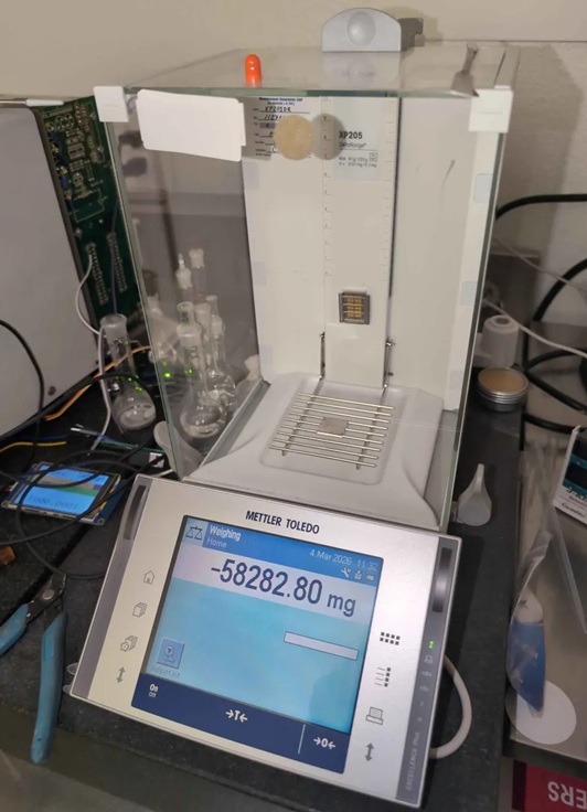
The finally fixed balance.
The Last Option: Checksum Patching
But what if we didn’t have that working dump? There’s another approach, though it comes with caveats that should make any reasonable person nervous.
The checksum itself is just a 32-bit value stored in flash at 0x003a3038 (in dump 1’s case). If you patch that value to match what the firmware actually computes, the memory check passes and the device boots. For dump 1, that means changing 0x8e49c65d to 0x8e49c65e.
Here’s the uncomfortable question: is the corruption only in the checksum storage location, or is there a bad bit somewhere in the actual firmware code? If it’s just the checksum slot — if that single bit flip happened to land in the least consequential place possible — then patching it is relatively safe. The firmware is actually fine; you’re just fixing the verification.
But if the corruption is somewhere in the actual code or data? You’re now running potentially corrupted firmware. Maybe it’s a single bit in a lookup table that causes occasional calculation errors. Maybe it’s in error handling code that only triggers in edge cases. Maybe it’s fine for months until it causes data corruption during a critical weighing operation.
We patched dump 1’s checksum and tested it. It booted. It ran. But I can’t in good conscience recommend this approach for anything beyond experimental tinkering. The risk profile is entirely dependent on where that corruption landed, and without exhaustively comparing against a known-good image, you simply don’t know.
Conclusion
Did we fix it? Sort of. Two scales are working again because we got lucky with the additional board having compatible firmware.
But here’s what bothers me: this shouldn’t have required any reverse engineering at all. The service manual documents the reflashing procedure. Mettler Toledo built e-Loader II for exactly this scenario. The firmware verification system is designed with the expectation that flash can fail. Yet performing the documented repair required dumping chips, writing custom Python to understand the checksum algorithm, and hoping one of the dumps was good.
The service manual itself probably wasn’t even meant for public access. It’s the kind of documentation that stays within authorized service networks. So even having the procedure documented doesn’t help most people who need it.
I worry this pattern will only get worse. As devices get more complex, the software becomes more critical to their operation. But manufacturers are increasingly treating firmware as a black box, with no official way for users to access or repair it. When something goes wrong, you’re left with a non-functional device and no path to fix it.